
BBMagic RELAY is four channel wireless relay with Bluetooth Low Energy (BLE) – Bluetooth Smart.
BBMagic RELAY functions
- Driving four relays
- Automatic RELAY_0 on (for 15 minutes) after power up – pin 17 configurable
- Supply voltage monitoring
- Light level measurement – pads for 10k photoresistor – values range: 0 to 255
- Two ADC 0 to 1,8V channels with 1mV resolution
- Communication: encrypted and digital signed Bluetooth Smart messages
- Chip temperature measurement.
- LED radio transmission indication – pin 2 configurable
- Easy to use Raspberry Pi 3 or zero W programming interface – bbmagic_lib_1.4 version or higher
How does BBMagic RELAY work?
After power up BBmagic RELAY sends ‘ALIVE’ messages every 60 seconds.
When receives demand message it turns relays on or off and immediately sends ‘ALIVE’ message to confirm: job is done.
What informations ‘ALIVE’ message contains
Library header file (bbmagic_lib.h) defines types of data sending by BBMagic RELAY
| bbm_buf[BBMAGIC_DEVICE_TYPE] | module type ; here is BBMAGIC_M_RELAY |
| bbm_buf[BBM_RELAY_V_SUP] | supply voltage ; divide this value by 71 (BBMAGIC_VCC_DIVIDER) to have power supply voltage in volts |
| bbm_buf[BBMAGIC_RELAY_ADV_TIME] | next ‘ALIVE’ message from BBMagic RELAY will arrive after this period of time ; multiply it by two to get time in seconds |
| bbm_buf[BBMAGIC_RELAYS_STATE] | four LSBs indicate four relays state. Bit set = Relay is ON, bit reset = Relay is OFF. Bit0 – RELAY_0…Bit3-RELAY_3 (see pinout picture below) |
| bbm_buf[BBM_RELAY_CHIP_TEMP] | BBMagic modules chip temperature in Celsius (U2 encoded) – after callibration can be interpreted as low accuracy ambient temperature |
| bbm_buf[BBM_RELAY_LIGHT] | light level ; from 0 to 255 |
| bbm_buf[BBM_RELAY_ADC_1_MSB] bbm_buf[BBM_RELAY_ADC_1_LSB] | voltage level on ADC_1 input in mV |
| bbm_buf[BBM_RELAY_ADC_2_MSB] bbm_buf[BBM_RELAY_ADC_2_LSB] | voltage level on ADC_2 input in mV |
| bbm_buf[BBMAGIC_RELAY_WORKTIME_0] | amount of time from modules power up – in seconds ; byte 0 – LSB |
| bbm_buf[BBMAGIC_RELAY_WORKTIME_1] | amount of time from modules power up – in seconds ; byte 1 |
| bbm_buf[BBMAGIC_RELAY_WORKTIME_2] | amount of time from modules power up – in seconds ; byte 2 |
| bbm_buf[BBMAGIC_RELAY_WORKTIME_3] | amount of time from modules power up – in seconds ; byte 3 – MSB |
| bbm_buf[BBM_RELAY_FIRM_0] | modules firmware version LSB |
| bbm_buf[BBM_RELAY_FIRM_1] | modules firmware version MSB |
| bbm_buf[BBMAGIC_DEVICE_ADDR_0] | modules address byte 0 – LSB |
| bbm_buf[BBMAGIC_DEVICE_ADDR_1] | modules address byte 1 |
| bbm_buf[BBMAGIC_DEVICE_ADDR_2] | modules address byte 2 |
| bbm_buf[BBMAGIC_DEVICE_ADDR_3] | modules address byte 3 |
| bbm_buf[BBMAGIC_DEVICE_ADDR_4] | modules address byte 4 |
| bbm_buf[BBMAGIC_DEVICE_ADDR_5] | modules address byte 5 – MSB |
| bbm_buf[BBMAGIC_DEVICE_RSSI] | radio signal strength indicator (RSSI) in dBm |
To drive BBMagic RELAY
You need to know modules bluetooth address and security key. Then add module to database:
bbm_relay_add("my_rel", "3B5D6868AA98", "2DFDA5070CD284A107A24F7e53572A7B38") ;
…and use one of bbmagic_lib_2.0 functions. This command below turns RELAY_0 and RELAY_3 on:
bbm_relay_on("my_rel", REL_CH0 | REL_CH3) ;
And now lets turn RELAY_3 off:
bbm_relay_off("my_rel", REL_CH3) ;
Pretty easy, isnt it? 🙂
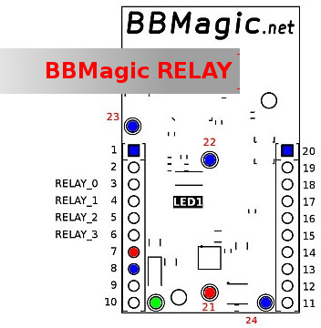
Pinout
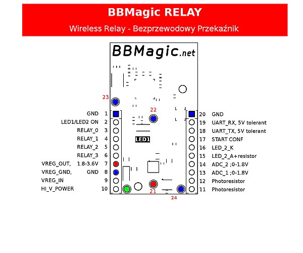
| Pin number | Description |
|---|---|
| 1,8,20,22,23,24 | GND – power and signal ground |
| 2 | Configuration of radio transmission indication:
|
| 3-6 | Four (RELAY_0…RELAY_3) outputs for relays driving (driving transistor needed) |
| 7,21 | Supply voltage 1,8V – 3,6V |
| 7,8,9 | Pads for voltage regulator if you decide to power BBMagic RELAY this way. Its identical like BBMagic METEO described here: Power it easy: BBMagic METEO Bluetooth Low Energy module |
| 10 | Supply voltage input for voltage regulator (Reverse polarity protected). Its identical like BBMagic METEO described here: Power it easy: BBMagic METEO Bluetooth Low Energy module |
| 11,12 | 10k photoresistor pads |
| 13,14 | Inputs of analog to digital converter ADC_1 and ADC_2. Available voltage range: 0V-1,8V ; Resolution: 1mV |
| 15,16 | Pads for alternative LED with series resistor. Pad 15 – LED anode with resistor, Pad 16 – LED cathode |
| 17 | If connected to ground (or pin 16) then after modules power up RELAY_0 output will be set for 15 minutes |
| 18,19 | Tx and Rx UART lines. Available voltage range: 0V-5V |
Wireless communication
- Bluetooth Low Energy also called as Bluetooth Smart
- Transferring data is encrypted and signed with AES-128
- You can collect and process data with Raspberry Pi, Arduino, etc.
- Direct communication with Raspberry Pi Zero W and Raspberry Pi 3 (both have Bluetooth Low Energy onboard chip)
- Library bbmagic_lib_1.4 for easy programming
Powering
BBMagic RELAY needs about 12mA of current. You can power it:
- from any source you want within 1,8V to 3,6V – connect to pins 7 (+) and 8 (-)
- with voltage regulator – connect ‘+’ to 10, and ‘-‘ to 22, 23 or 24. Onboard pads 7,8,9 for TO-92 voltage regulator (ex. L78L33, TS2950CT-3.3, LP2950CZ-3.3RAG, MCP1702-3302E, LM2936Z-3.3, LT1121CZ-3.3). Learn more about voltage reg here: Power it easy: BBMagic METEO Bluetooth Low Energy module